The Louvre, Abu Dhabi
by Jean Nouvel
status: under-construction
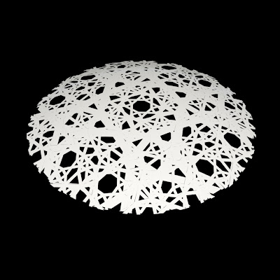
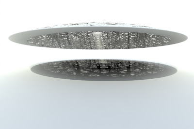
“A large, shallow dome, 180m in diameter, floats above the collection of buildings, with only four support points around its perimeter truss. The dome unites this micro-city, and takes up the Islamic tradition of the perforated screen and the use of self- similarity and fractal organization of patterning to create a special micro-climate below. The space beneath is animated by the shadow play caused by the modulation of light by the complex, lacy mesh of small openings across the dome’s surface, reflected on the buildings and the water of the inlet.”
Study of the initial duplication of the fractal pattern
Study of the initial duplication and 12.5 degrees step rotations of the fractal pattern
Result of the initial duplication and rotation of the fractal pattern
Fractal pattern studies
Fractal pattern shadow studies:
This experiment was done using a software called modo. The pattern in this rendering is procedural, not generated from the previous diagrams.
This experiment was done using a software called modo. The pattern in this case is a direct translation of the diagrams into a three-dimensional surface.
Step1: pattern based curtain panel
The first step was to create a pattern based curtain panel family.
Step1.5: alternative pattern based family
While the previous family is the most basic form that can be duplicated to generate the pattern, this alternative family contains a more complex form that can generate the same pattern. However, because the first pattern fits within a smaller foot print, it will morph more efficiently with the dome shape. Thus, the family in Step1 was chosen to move forward.
Step2: massing family for the volumes
The height of the whole building and all its masses is controlled by a multi- plier. This multiplier allows for the change of all the volumes in the design proportionally. This in return will maintain the relationships between all the volumes. Dome at this stage was only a place-holder in the model.
Step3: dome massing family
The creation of the massing for the dome was the trickiest part of this model. While it might seem very simple to accomplish with a revolve, the outcome of a revolve would not work in this case. The design of the dome requires that the pattern is applied to the dome uniformly, while the revolve will result in small subdivisions at the center and large subdivisions towards the perimeter as in #1. In order to solve this problem, a lot of experiments were done including importing the form from external modelers. However, in the end, using a section of a Torus, while not perfect, it gave the best results.


Step4: a different method for dome making
#1 is where the profiles are lofted to make a surface.
#2 a void mass is then used to subtract the unnessisary parts from the dome
#3 shows the result of the subtraction
#4 shows the pattern applied uniformally on the surface of the dome

Step5: rotation parameter
As per the diagrams of the fractal pattern, each layer rotates 12.5 degrees at every step. Thus, each layer of the dome’s exterior shell has a rotation parameter.
Step6: passing parameters
The parameters of each of the exterior layers of the dome are passed to the project. The parameters include:
U subdivision for the curtain panel
V subdivision for the curtain panel
Rotation angle
Pattern based family’s frame width
Pattern based family’s frame depth
Pattern based family’s material
Step9: final model rendering
a. The revit model was exported using SAT format.
b. The SAT format was brought into another software called MoI, which is a NURBS modeler.
c. The model was then exported from MoI using Lightwave format.
d. Finally, the model was brought into modo for final renderings.
note: the reason for this long process is that MoI can handle and export quad and n-gons unlike Rhino, and Revit in most cases.


hello, is this possible to share your 3D model?
ReplyDelete